


 عربى
عربى 中文简体
中文简体Search by posts
Calendar
Product Categories
Industry News
 By Admin
How many PSI do I need to run an air impact wrench?
Operating an air impact wrench effectively requires a clear understanding of pneumatic pressure and air flow mechanics. A standard air impact wrench requires 90 PSI, which stands for pounds per square inch, measured directly at the tool inlet while the trigger is fully depressed. While 90 PSI is the industry standard operating pressure for almost all light to heavy duty pneumatic tools, achieving that exact pressure during active operation involves much more than simply adjusting the regulator dial on an air compressor.
Pneumatic tools rely on a balance between static pressure and dynamic pressure. Static pressure is the force stored in the compressor tank when no air is flowing through the system. Dynamic pressure is the actual force delivered to the internal air motor of the air impact wrench while the tool is running. If an air system is set to 90 PSI at rest, the pressure often drops significantly as soon as the trigger is pulled. Consequently, understanding how to configure an air compressor system, select the correct hose diameters, minimize line restrictions, and maintain proper volume ensures that an air impact wrench operates at its intended torque capacity without damaging internal components.
Understanding PSI and Its Role in Pneumatic Tool Performance
Pounds per square inch measures the intensity of force exerted by compressed air within a enclosed environment. In the context of an air impact wrench, PSI provides the initial physical pressure required to drive the internal rotor, which spins the hammer mechanism against the anvil to generate rotational force.
[Image: Close up view of an air impact wrench connected to an air line regulator showing a pressure gauge reading exactly 90 PSI during operation]
What is PSI and Why Does It Matter for Pneumatic Tools?
Compressed air functions as an energy storage medium. When ambient air is compressed into a smaller volume inside a receiver tank, the potential energy increases proportionally. When this compressed air is released through an air line into an air impact wrench, it expands rapidly against the vanes of the tool air motor.
PSI represents the density of this energy delivery. If the operating pressure is too low, the air motor will not generate enough speed to sling the internal hammers with sufficient momentum. As a result, the tool fails to reach its rated breakaway torque. Conversely, supplying an excessively high PSI forces the motor to spin beyond its engineered stress limits, accelerating wear on internal bearings, vanes, and impact hammers while posing safety risks to the operator.
The Direct Relationship Between PSI and Torque Output
The torque output of an air impact wrench is directly tied to the dynamic air pressure delivered to its intake port. Pneumatic tool manufacturers engineer their impact mechanisms, including twin hammer, pin clutch, and rocking dog designs, to reach maximum efficiency at a specific pressure threshold, which is almost universally established at 90 PSI.
When dynamic pressure drops from 90 PSI down to 70 PSI, the torque output does not drop by a mere fraction. The loss in rotational momentum can diminish total breaking torque by up to thirty percent. This drastic drop occurs because hammer impact energy relies on both mass and velocity. Lower pressure reduces rotor velocity exponentially decreasing the kinetic energy transferred during each strike. Supplying excessive pressure above recommended levels might briefly yield higher torque, but it subjects the housing and drive shaft to excessive stress, leading to premature metal fatigue and seal failure.
Standard PSI Requirements for Different Impact Wrench Sizes
While 90 PSI remains the foundational baseline across the industry, variations exist depending on tool scale, application demands, and industrial environments. The table below outlines standard operational pressures across different tool classes.
|
Impact Wrench Drive Size |
Recommended Dynamic PSI |
Average Working Pressure Range |
Primary Application Environment |
|---|---|---|---|
|
One Quarter Inch Drive |
90 PSI |
85 to 90 PSI |
Precision automotive trim, small engine repair |
|
Three Eighths Inch Drive |
90 PSI |
85 to 95 PSI |
General automotive, engine bay maintenance |
|
Half Inch Drive |
90 PSI |
90 to 100 PSI |
Wheel lug nuts, suspension work, light industrial |
|
Three Quarter Inch Drive |
90 to 100 PSI |
90 to 110 PSI |
Heavy equipment, commercial truck service |
|
One Inch Drive |
90 to 110 PSI |
100 to 120 PSI |
Industrial construction, fleet maintenance, rail |
Smaller drive tools require strict adherence to 90 PSI due to delicate internal air motor vanes. Large industrial tools designed for commercial vehicle service sometimes utilize slightly higher operating pressures up to 110 or 120 PSI, provided the manufacturer explicitly approves the tool for heavy duty line supply systems.
The Critical Distinction Between PSI and CFM
One of the most frequent errors when operating an air impact wrench is focusing solely on PSI while ignoring CFM, which stands for cubic feet per minute. While PSI measures the force or pressure of the air, CFM measures the volume of air flowing through the system over a given period.
[Image: Illustration showing the difference between air pressure PSI measured on a gauge and air volume CFM flowing through a wide hose versus a narrow hose]
Why High PSI Alone Will Not Operate Your Impact Wrench
An air compressor tank can be pressurized to 150 PSI, but if the air compressor pump cannot supply enough CFM, or if the air hose is too narrow to transport the required volume of air, an air impact wrench will stall almost immediately upon pulling the trigger.
Think of PSI as the voltage in an electrical system and CFM as the amperage. Alternatively, picture a pressure washer compared to a fire hose. A pressure washer operates at extremely high PSI but moves a small volume of water. It cannot quickly fill a large swimming pool. A fire hose operates at moderate pressure but moves a massive volume of water per minute. An air impact wrench requires a massive volume of air delivered rapidly to maintain its spinning speed under load. Without sufficient CFM, the 90 PSI stored in the hose collapses within seconds, stalling the hammer mechanism.
Calculating CFM Demands for Continuous Work Cycles
Air consumption rates vary depending on the drive size and internal motor design of the air impact wrench. Most manufacturers list a average CFM rating based on a duty cycle of fifteen to twenty five percent usage, which reflects intermittent operation such as loosening five lug nuts on a wheel assembly.
To determine the true requirement for continuous operation or demanding shop environments, multiply the manufacturer average CFM rating by four. The following guide illustrates typical volume requirements for various drive sizes operating at 90 PSI:
-
One quarter inch air impact wrench: Requires 2 to 4 CFM at 90 PSI
-
Three eighths inch air impact wrench: Requires 3 to 5 CFM at 90 PSI
-
Half inch air impact wrench: Requires 4 to 6 CFM at 90 PSI
-
Three quarter inch air impact wrench: Requires 7 to 10 CFM at 90 PSI
-
One inch air impact wrench: Requires 10 to 15 CFM at 90 PSI
When selecting an air compressor, ensure its continuous output rating exceeds the requirement of your largest air impact wrench by at least twenty five percent to allow proper cooling and prevent the compressor pump from running continuously without resting.
How Compressor Tank Size Offsets Air Volume Limitations
The physical volume of an air compressor receiver tank acts as a practical buffer between the compressor pump output and the air impact wrench consumption rate. Small portable air compressors with small tanks, such as six gallon pancake models, can achieve 90 PSI easily. However, their small pumps might only deliver 2.5 CFM.
When a half inch air impact wrench requiring 5 CFM is connected to a small tank, the tool consumes stored air faster than the pump can replenish it. The pressure rapidly drops below the working threshold of 90 PSI within three to five seconds of continuous trigger action. Once the pressure drops, the impact mechanism loses striking force.
A larger tank, such as thirty to sixty gallons, stores enough volume at elevated pressure, typically 135 to 175 PSI, to allow the air impact wrench to run continuously for long periods. The regulator on the tank steps down this higher storage pressure to a steady 90 PSI at the hose output, shielding the tool from immediate pressure drops while the pump runs to catch up.
Air Impact Wrench Operating Requirements by Drive Size
Different tool drive sizes serve distinct mechanical applications, ranging from delicate assembly work to heavy diesel engine teardowns. Understanding the air volume and pressure demands specific to each drive size helps build an efficient pneumatic system.
One Quarter Inch and Three Eighths Inch Drive Air Impact Wrenches
Small format air impact wrenches are engineered for tight spaces, engine bays, dashboard assemblies, and light machinery maintenance. Because their internal air motors are compact, their physical volume requirements are relatively modest.
-
Standard Dynamic Pressure: 90 PSI
-
Volume Consumption: 2 to 4 CFM
-
Minimum Recommended Air Hose Inside Diameter: One quarter inch
-
Ideal Applications: Small engine repair, motorcycle maintenance, interior trim work
These tools are sensitive to over-pressurization. Supplying pressure beyond 90 PSI can rapidly ruin small rotary vanes and crack lightweight aluminum or composite housings.
Standard Half Inch Drive Air Impact Wrenches
The half inch drive air impact wrench is the workhorse of automotive repair shops, tire centers, and home garages. It delivers a balanced combination of high torque and maneuverability, making it the primary choice for removing lug nuts, suspension bolts, and rusted chassis fasteners.
[Image: Mechanic using a half inch drive air impact wrench to remove lug nuts from a truck wheel in an automotive shop]
-
Standard Dynamic Pressure: 90 PSI
-
Volume Consumption: 4.5 to 6 CFM
-
Minimum Recommended Air Hose Inside Diameter: Three eighths inch
-
Ideal Applications: Automotive wheel service, suspension teardowns, farm equipment repair
To achieve the advertised maximum torque on a half inch air impact wrench, using a three eighths inch inside diameter hose is crucial. Connecting a half inch tool to a standard one quarter inch hose severely throttles air volume, dropping effective torque by as much as forty percent.
Heavy Duty Three Quarter Inch and One Inch Drive Models
Industrial air impact wrenches are designed for heavy commercial service, structural steel construction, agricultural machinery, and heavy equipment maintenance. These tools feature oversized air motors designed to strike with immense force to break free seized fasteners.
-
Standard Dynamic Pressure: 90 to 110 PSI
-
Volume Consumption: 8 to 15 CFM
-
Minimum Recommended Air Hose Inside Diameter: Half inch or larger
-
Ideal Applications: Commercial fleet maintenance, tractor service, industrial assembly
Due to the massive air flow requirements of these heavy duty tools, standard quick disconnect fittings and small air regulators will create bottlenecking. They require high flow couplers, wide diameter supply lines, and large capacity air compressors to deliver adequate volume.
System Pressure Drops and How to Prevent Dynamic Loss
Setting the tank outlet regulator to 90 PSI rarely guarantees that 90 PSI reaches the inlet of your air impact wrench. Air traveling through a pneumatic system encounters friction, turbulence, and structural restrictions, all of which contribute to a drop in line pressure.
The Hidden Threat of Frictional Loss in Air Hoses
As compressed air passes through an air hose, the outer edges of the air stream drag against the inner wall of the hose material. This friction converts fluid energy into heat, causing a gradual reduction in line pressure over the length of the run.
The longer the hose, the greater the pressure drop created by internal friction. For instance, air passing through a fifty foot hose will experience twice the friction loss compared to air traveling through a twenty five foot hose of the same diameter. If the inner wall of the hose is rough or kinked, pressure loss accelerates further.
Selecting the Right Air Hose Diameter and Length
Selecting an appropriate air hose diameter is the single most effective way to prevent pressure drop between the compressor tank and the air impact wrench. Hose diameter refers strictly to the inside diameter, not the outer casing thickness.
|
Hose Inside Diameter |
Hose Length |
Air Flow Capacity at 90 PSI |
Suitability for Half Inch Impact Wrench |
|---|---|---|---|
|
One Quarter Inch |
25 Feet |
Restricted Flow |
Poor (Significant Pressure Drop) |
|
One Quarter Inch |
50 Feet |
Severely Restricted Flow |
Unusable for Full Torque Output |
|
Three Eighths Inch |
25 Feet |
Optimal Flow |
Ideal Performance |
|
Three Eighths Inch |
50 Feet |
Moderate Flow |
Good (Minor Regulator Adjustment Needed) |
|
Half Inch |
50 Feet |
High Flow |
Excellent (Minimal Friction Loss) |
|
Half Inch |
100 Feet |
High Flow Capacity |
Recommended for Long Distance Runs |
To compensate for line loss over a fifty foot three eighths inch hose, adjust the main compressor regulator to roughly 105 PSI static pressure. When the trigger on the air impact wrench is squeezed, the dynamic pressure will drop down to the target level of 90 PSI at the tool intake port.
The Impact of Quick Couplers, Fittings, and Filter Regulators
Air hoses are not the only source of airflow restriction in a pneumatic setup. Every quick disconnect coupler, valve, elbow, and filter unit installed along the line creates a point of localized restriction.
Standard automotive style quick couplers have tiny internal valve orifices that restrict air volume dramatically. Replacing standard brass quick couplers with high flow pneumatic fittings allows up to twice as much air volume to pass through the same line connection. Furthermore, installing moisture filters and regulators directly at the wall pipe outlet rather than right on the tool handle reduces unnecessary dead weight while preserving air volume delivery.
Step by Step Guide to Setting Up Your Air System for Maximum Efficiency
Achieving a consistent 90 PSI working pressure requires configuring the entire compressed air delivery chain. Follow this step by step workflow to configure an optimal air supply setup.
[Image: Diagram showing an ideal shop air setup including compressor, moisture trap, regulator, lubricator, high flow fittings, and proper hose routing to an air impact wrench]
Step 1: Establish Proper Tank Pressure Settings
Ensure your air compressor pressure switch is set to maintain a healthy storage differential. A typical shop compressor should cut in around 110 PSI and cut out around 140 to 175 PSI. Storing air at high pressure ensures a steady reservoir that can feed the line regulator consistently.
Step 2: Configure In Line Regulators and Moisture Traps
Mount a clean filter regulator unit at the compressor discharge port or along the hard shop piping network. Drain the water collector bowl daily to prevent accumulated moisture from washing into the air line. Set the regulator knob to roughly 100 to 105 PSI as a baseline starting point to offset expected hose friction loss.
Step 3: Install High Flow Couplers and Correct Hoses
Attach high flow pneumatic couplers to the air supply line. Connect a three eighths inch inside diameter rubber or polyurethane air hose measuring no longer than necessary for the job site. Avoid using tight coil hoses for high demand tools like a half inch air impact wrench, as coiled designs create high internal friction and severe flow restrictions.
Step 4: Test Dynamic Pressure Under Active Load Conditions
The truest test of an air system takes place under dynamic load. Install an in line pressure gauge directly between the end of the air hose and the air impact wrench intake port.
Observe the gauge reading while the tool is idle. It will display static pressure, such as 105 PSI. Now, press the impact wrench anvil firmly against a solid heavy fastener or socket test bench and depress the trigger completely so the motor runs under load. Look at the inline gauge reading. Adjust the main line regulator until the inline gauge reads exactly 90 PSI while the tool trigger is actively pulled.
Diagnostic Table: Air Supply Troubleshooting for Air Impact Wrenches
When an air impact wrench lacks power or operates inconsistently, the issue usually stems from an air delivery bottleneck rather than internal mechanical failure. Use this troubleshooting guide to identify and resolve common pressure issues.
|
Symptom |
Probable Cause |
Corrective Action |
|---|---|---|
|
Tool runs slowly with low torque; static pressure shows 90 PSI |
Undersized air hose diameter or restrictive quick couplers throttling CFM volume |
Upgrade to a three eighths inch inside diameter hose and install high flow quick connect fittings |
|
Pressure gauge drops drastically when trigger is squeezed |
Air compressor tank size is too small or compressor regulator is set too low |
Increase main regulator setting slightly or upgrade to a larger receiver tank to increase buffer volume |
|
Air impact wrench lacks power despite correct pressure and hose size |
Accumulated moisture, dirt, or lack of lubrication inside the pneumatic motor |
Flush the air intake with pneumatic tool cleaner, blow clear, and add ten drops of air tool oil |
|
Sudden drop in line pressure accompanied by a hiss |
Leaking quick connect fittings, damaged hose casing, or worn internal tool gaskets |
Replace worn fittings, inspect hose length for micro-punctures, and rebuild tool intake seals |
|
Tool freezes or stutters during extended use |
Moisture freezing inside the exhaust ports due to compressed air expansion |
Install a dedicated air dryer moisture separator unit at the compressor outlet |
Common Air Supply Mistakes That Reduce Air Impact Wrench Torque
Avoiding common configuration oversights will preserve tool performance, extend compressor lifespan, and eliminate frustration during demanding tasks.
Running Undersized Hoses on High Demand Tools
Using a one quarter inch air hose on a half inch air impact wrench is one of the most widespread errors in automotive shops and home garages. While a one quarter inch hose is flexible and easy to handle, its small internal channel chokes off the air volume required by larger rotary motors. Even if the pressure gauge reads 90 PSI at rest, the high friction loss starves the tool the moment torque is required, causing severe power drops.
Misinterpreting Gauge Pressure vs Dynamic Flow Pressure
Adjusting an air regulator to 90 PSI while the tool is silent is a false reading. That static reading only reflects pressure when air is motionless. The moment the trigger opens, air begins to move, friction takes effect, and line pressure drops. Always adjust regulator settings based on dynamic pressure readings taken while the air impact wrench is operating under actual load.
Neglecting Moisture Removal and In Line Lubrication
Water vapor is an inevitable byproduct of air compression. As warm compressed air cools inside receiver tanks and delivery pipes, water vapor condenses into liquid water. If this water travels down the line into the air impact wrench, it strips away protective oil, rusts precision steel rotor vanes, and causes premature motor seize.
[Image: Hands holding pneumatic tool oil and applying several drops into the air inlet port of a half inch drive air impact wrench]
To prevent corrosion:
-
Drain the compressor tank drain valve daily
-
Install a dedicated water separator trap near the compressor outlet
-
Add five to ten drops of specialized pneumatic tool oil directly into the tool air inlet before every work session, or install an in line lubricator device
Operational Safety Guidelines and Maintenance Practices
Operating pneumatic machinery safely requires adherence to pressure boundaries, safe hose management, and consistent maintenance schedules.
Safe Operating Limits and Over-pressurization Hazards
Never exceed the maximum pressure rating stamped on the tool housing, which is generally 90 PSI dynamic pressure unless specified otherwise by the manufacturer. Cracking the regulator open to 130 or 150 PSI to break free a stubborn lug nut is hazardous. Extreme air pressure can shatter impact sockets, burst air hoses, cause internal drive hammers to disintegrate, or crack composite tool bodies. If a fastener remains stuck at 90 PSI dynamic pressure, use a larger drive air impact wrench, apply penetrating fluid, or utilize heat rather than over-pressurizing the smaller tool.
Daily Maintenance Routines to Protect Pneumatic Motors
A simple maintenance routine ensures your air impact wrench performs reliably for years:
-
Drain moisture from the air compressor receiver tank prior to beginning work
-
Check air line hoses for cuts, cracks, or signs of wear along crimped ends
-
Apply five to ten drops of pneumatic tool oil into the air inlet nipple prior to connecting the air hose
-
Run the tool briefly for three seconds to distribute oil across internal rotary vanes
-
Verify that safety retaining rings or pin detents on the drive anvil are clean and functional
Storage Practices to Prevent Internal Corrosion
When storing an air impact wrench at the end of a workday or for extended periods:
Disconnect the tool from the air line to relieve internal pressure. Pour a few extra drops of air tool oil directly into the air inlet and depress the trigger briefly to coat internal steel surfaces with a protective oil film. Store the air impact wrench in a clean, dry environment off the workshop floor to prevent moisture, dirt, and metallic dust from entering the air inlet port. Use dust caps over the air inlet fitting when the tool is stored in a toolbox to block debris accumulation.
Recommended products
-
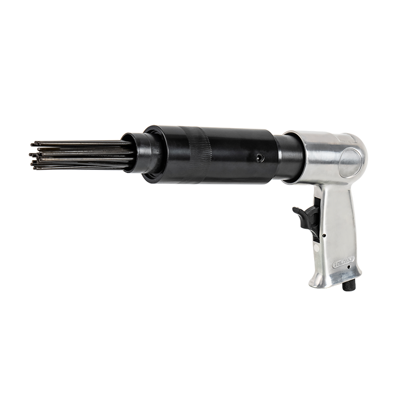
RH-464 Pneumatic Corner Needle Scaler
-
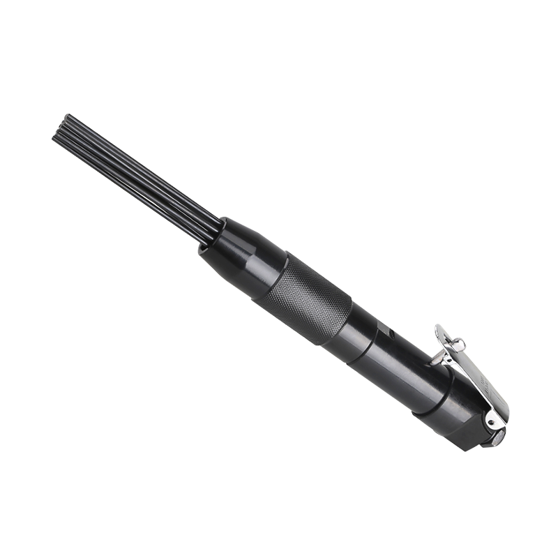
RH-460 Mini Compact Pneumatic Air Needle Scaler
-
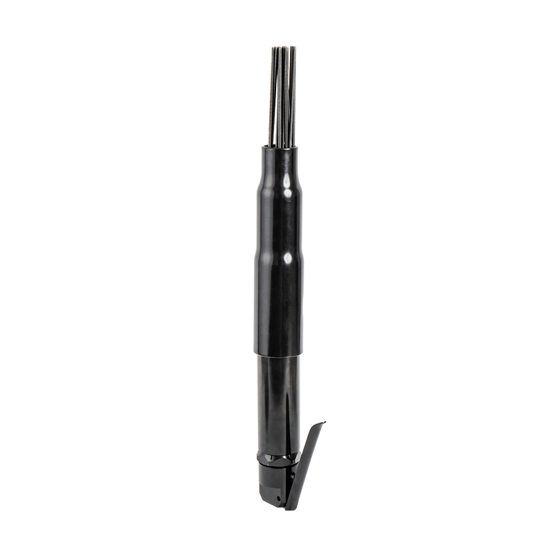
RH-462 Portable Industrial Straight Needle Scaler
-
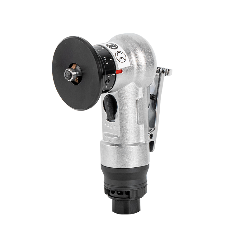
RH-7034C Portable Pneumatic Chamfering Machine
-
RH-7034B Central Pneumatic 4" Air Angle Grinder
-
RH-7034D 7" Hand Held Angle Grinder
-
RH-160 1/2" Drive Single Hammer Air Pneumatic Impact Wrench
-
RH-160K Cordless Electric Rechargeable Air Impact Wrench Kit
-
RH-112 1/2" Universal Electric Ratchet Wrench Hand Tool
-
RH-128 1/2" High Torque Electric Ratchet Wrench
-
RH-138 3/8" Long Head Portable Cordless Electric Ratchet Wrench
-
RH-148 1/4" Electric Battery Ratchet Wrench
CONTACT OUR EXPERTS
AND GET A FREE CONSULTATION!
Ningbo Haishu Renhao Pneumatic Co., Ltd.
 Address: Jiangbei District Ningbo City in Zhejiang Province by the Keli industrial ParkL Building 15th
 Phone: +86-139 0668 0779
 Tel: +86-139 0668 0779
 Fax: +86-139 0668 0779
 E-mail:[email protected]


